|
|
Creating an Aircraft Configuration File
An aircraft configuration file consists of 6 sections:
- General aircraft data
- Flap positions and max operating speeds
- Stall speed, Min/Max manoeuvring speeds
- Take-off Flap Retract Schedule
- Landing Flap Extend Schedule
- Take-off V-Speeds
- Take-off data
- Climb data
- Cruise data
- Descent data
- Approach data
- EICAS Messages
The first section is used to define general aircraft data, this section is required.
The next four sections are related to the aircraft’s flap configurations, limitations and extend/retract schedules during take-off and landing. These sections are optional, but when they are not present, no related speed data will off course be displayed in the primary flight display and the EICAS display will not show the correct flap position.
The five remaining sections are all related to VNAV calculations, these sections are required.
The aircraft file is NOT case sensitive so you don’t need to worry about that.
You can put comments in the file by placing a ‘#’, everything on the same line after a ‘#’ will be ignored.
|
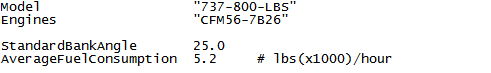
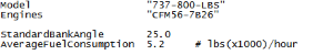
General aircraft data
The first two items, the “model” and “engines” in this section are aircraft identity items and will appear in the “IDENT” page in the FMC.
You can name your aircraft and engines however you like but it’s best off course to give them a name that makes sense, for example if you’re creating a Boeing 737-800 aircraft file you might want to put “B738” or “737-800” next to the “Model” keyword.
The engines you can also name what you like but if you want to keep it realistic, you would follow the international standards for engine model identification, these can be found here
The value next to the keyword “StandardBankAngle” defines the bank limit of the aircraft and is used when calculating the radius of turn when displaying the route on the HIS screen. This value is a floating point value and is in degrees. 25 degrees is the standard value for this field and I don’t think you would need to change that unless you’re building a configuration file for some very exotic aircraft.
The value associated with the keyword “AverageFuelConsumption” defines how much weight of fuel the aircraft consumes on average per hour.
So this is a weight value and can be in any unit of measurement you like, i.e. you can use metric tons or imperial tons, lbs x 1000, kgs, lbs, … it does not matter.
However, it is important that the unit of measurement you use here is CONSISTENT throughout the entire aircraft configuration file. You will be definng approach/climb/cruise/descent/approach data for specific aircraft weights in the following section, you MUST use the same unit of measurement everywhere.
Also, the unit of measurement you use here will be the unit of measurement you will work in when entering gross weight/fuel weight/zero fuel weight in the “INIT REF” page in the FMC.
|
General
|
Flap Speeds
|
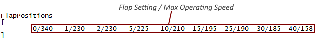
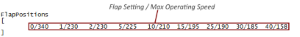
Flap positions and max operating speeds
The FlapPositions table is used to define the different flap settings and corresponding max operating speeds.
The table starts with the keywords “FlapPositions”, the data is defined within square brackets […].
Each data element within the brackets consists of a flap position and a corresponding maximum operating speed, separated by a forward slash ‘/’.
It is important every position is defined including the zero position, in ascending order. If not there will be inconsistencies displaying the correct flap position in the EICAS display.
|
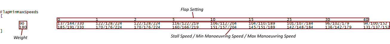
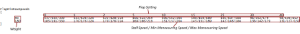
Stall speed, Min/Max manoeuvring speeds
The FlapMinMaxSpeeds table defines the stall, minimum and maximum manoeuvring speed for a given flap setting at a given weight.
The table starts with the keyword “FlapMinMaxSpeeds”, the data is defined within square brackets […].
The first row contains the different Flap settings for your aircraft in ascending order. It is important every position is defined including the zero position, in ascending order.
Similarly the first column defines the different weights you would want to define a specific data element for. You do not need to define a data row for every weight you possibly want to fly the aircraft at, if the current weight of you aircraft falls between 2 of the defined weights in the table, iFMS will use linear interpolation to calculate the corresponding speed values.
Each data element within brackets consists of a stall speed, min manoeuvring speed and a max manoeuvring speed, separated by a forward slash ‘/’.
|
Speed Limits
|
Flap Schedule

|
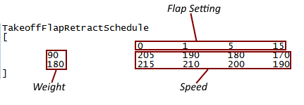
Take-off Flap Retract Schedule and
Landing Flap Extend Schedule
The TakeoffFlapRetractSchedule table and the LandingFlapExtendSchedule table define the speeds at which the flaps are retracted/extended during take-off/landing. These speeds are displayed as markings on the Primary Flight Display.
The tables starts with the keywords “TakeoffFlapRetractSchedule” and “LandingFlapExtendSchedule”, the data is defined within square brackets […].
The first row contains the different Flap settings for your aircraft in ascending order. It is important every position is defined including the zero position, in ascending order.
Similarly the first column defines the different weights you would want to define a specific data element for. You do not need to define a data row for every weight you possibly want to fly the aircraft at, if the current weight of you aircraft falls between 2 of the defined weights in the table, iFMS will use linear interpolation to calculate the corresponding speed values.
Each data element within brackets defines the retract/extend speed for that flap position/weight combination, separated by a forward slash ‘/’.
|
Take-off V-Speeds
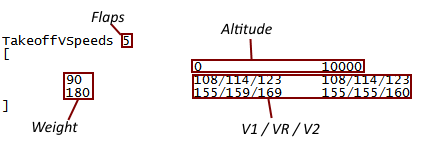
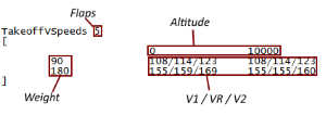
The TakeoffVSpeeds table defines the speeds at which V1, VR and V2 markings are displayed on the Primary Flight Display.
TakeoffVSpeeds data is defined in tables per flap setting. A TakeoffVSpeeds data table starts with the keywords “TakeoffVSpeeds”, followed by the flap setting relative to that table, the actual data is defined within square brackets […].
You can provide as many different flap setting TakeoffVSpeeds tables as is relevant for your aircraft.
The first row of the data table contains altitudes in ascending order at which you wish to define different data for your aircraft.
Similarly the first column defines the different weights you would want to define a specific data element for. You do not need to define a data row/column for every weight/altitude combination you possibly want to fly the aircraft at, if the current weight/altitude of you aircraft falls between 2 of the defined points in the table, iFMS will use linear interpolation to calculate the corresponding speed values.
Each data element within brackets defines the V1, VR, V2 speed for that altitude/weight combination, separated by a forward slash ‘/’.
|
V-Speeds
|
Take-off Data
|
Take-off & Approach data
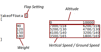
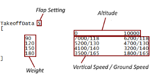
Take-off and approach data tables define the vertical speeds and ground speeds for the aircraft when it is climbing below the acceleration height (takeoff) or descending below the deceleration height (approach). It is important to note that the word “height” here means height above the takeoff/landing runway.
The data tables are formatted in the same way and start with the keywords “TakeoffData” or “ApproachData” followed by the flap setting relative to that table, the actual data is defined within square brackets […].
You can provide as many different flap setting tables as is relevant for your aircraft.
The first row of the data table contains altitudes in ascending order at which you wish to define different data for your aircraft.
Similarly the first column defines the different weights you would want to define a specific data element for. You do not need to define a data row/column for every weight/altitude combination you possibly want to fly the aircraft at, if the current weight/altitude of you aircraft falls between 2 of the defined points in the table, iFMS will use linear interpolation to calculate the corresponding values.
Each data element within brackets defines the vertical speed in FPM and ground speed in KT for that altitude/weight combination, separated by a forward slash ‘/’.
|
Climb and descent data
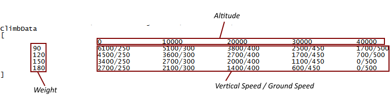
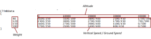
Climb and descent data is defined in tables similar to the takeoff/approach data tables, the only difference being that you have only one table to define, there are no different tables for different flap settings here as you would generally not fly an aircraft in the climb or descent phase with flaps.
Climb/descent data tables start with the keywords “Climbdata”/“DescentData” and again the actual data is defined within square brackets […].
Again the data defines the vectical speed and ground speed per weight per altitude and again vertical speed values have to be positive in the climb table and negative in the descent table.
|
Climb Data
|
Cruise Data
|
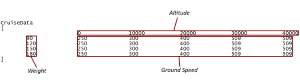
Cruise data
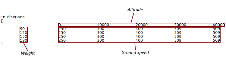
Cruise data is defined in a slightly different table, the table starts with the keyword “CruiseData” and yet again the data data is defined within square brackets […].
The main difference in this table compared to the others is that there is no vertical speed data (you’re cruising so there should not be any), the data elements only define ground speed in knots.
That is the only difference, like with the other tables the data is defined per weight/altitude combination.
|
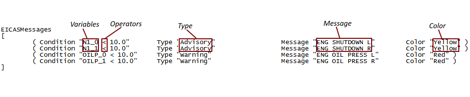
EICAS Messages
EICAS messages are messages that are displayed on the right hand side in the primary EICAS displays.
There are 4 different types of messages: Warning, Caution, Advisory, Status; and these are displayed in different colours:
Red, Yellow, White, Green, Cyan, which is configurable.
Warning messages will always be displayed on top, then Cautions, the Advisories and finally Statuses, if the type is equal they will be displayed in the order they appear in the aircraft configuration file.
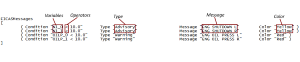
When and how messages are displayed needs to be configured in the EICAS Messages table, the table starts with the keyword “EICASMessages” and the data is defined within square brackets […].
Messages are displayed based on “conditions” defined in the table, a condition checks for a test to be true, if it is true the corresponding message will be displayed.
A condition checks if the value of a flight simulator variable is greater than (‘>’), less than (‘<’), equals to (‘=’) or not equals to (‘!’) a fixed value. If this is the case a corresponding message will be displayed with the colour/priority defined in the condition.
Variables
The variables that can be used in the conditions are listed below:
- GEAR_index
- FLAPS
- FLAPSTGT
- SPOILERS
- SPOILERSARMED
- N1_index
- N2_index
- EPR_index
- EGT_index
- OILP_index
- OILT_index
- OILQ_index
- VIB_index
- HYDP_index
- HYDQ_index
- FF_index
- FP_index
- CENTRETANK1
- CENTRETANK2
- CENTRETANK2
- LEFTMAINTANK
- RIGHTMAINTANK
- LEFTAUXTANK
- RIGHTAUXTANK
- LEFTTIPTANK
- RIGHTTIPTANK
Where the variable below ends in "_index", there are multiple values for this variable (for example in case of multiple engines), and the word index should be replaced with the index of the variable. this is "zero based" (meaning 0 being the first).
For example, in the standard FSX 737, "N1_0" will give you the left engine N1 value, "N1_1" will return the right engine N1 value.
|
EICAS Messages
|
|
|
Need Help?
Example aircraft files can be downloaded from the iFMS website downloads page.
I’m happy to respond to any questions you might have about creating your own aircraft files, or questions about iFMS in general, just contact me directly or through the iFMS website feedback page.
Finally, if you wish to share your own created aircraft files with the flight simulator community, just email them to me, I will review them and put them on the iFMS website.
Blue Skies
Michael De Feyter
|